AP Physics C EM Crib Notes
Electricity
- $Q$ charge (analogue of weight)
- $F_E$ electric force (analogue of G force)
- $E$ electric field (analogue of G field)
- $\Phi_E$ flux, $\Phi_E = E \cdot A$, intuitively number of E field lines passing through some area
- $V$ electric potential (analogue of G potential)
Gauss’ Law: $\int_A E_\perp \, da = \frac{Q_{\text{enclosed}}}{\epsilon_0}$, where $\epsilon_0$ is the vacuum dielectric permittivity constant.
A conductor is an object in which electric charge can freely flow through, a insulator is an object which electric charge cannot.
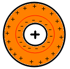
We will assume that inside a conductor, there is no net flow of charges, or the charges will move until the field is zero. Therefore, we can infer that the electric potential inside the conductor is constant throughout. This also means the electric field must be perpendicular to the surface of the conductor. Using Gauss’ Law, we can enclose any area strictly inside the conductor. Since $E=0$, we must conclude that $Q_{\text{enclosed}}=0$. Therefore, all charge of a conductor must be on it’s surface. This has interesting consequences for conductors with “holes” in them. To ensure that Gauss’ Law holds inside the red circle below, the charges must be arranged as such.
Using Gauss’ Law on a point charge $q$ with $A$ being the surface area of a sphere of radius $r$, we obtain $E = \frac{q}{4 \pi r^2 \epsilon_0} = k \frac{q}{r^2}$, where we have $k = \frac{1}{4 \pi \epsilon_0}$.
For an infinite plane with charge density $\sigma$, we know that the field lines will be perpendicular to the entire plane by symmetry. Let us consider a cuboid with sides of area $A$ parallel to the infinite plane. By Gauss’ Law, $E = \frac{A\sigma}{2A\epsilon_0} = \frac{\sigma}{2\epsilon_0} = 2\pi k \sigma$. Note that if we have two infinite parallel planes with charge densities $\sigma$ and $-\sigma$, this force will be doubled to $\frac{\sigma}{\epsilon_0}$.
The difference in potential is defined as $V = \int \vec E \, d\vec x$. To assign values to potential, we take $V_\infty = 0$ as convention. A positive would want to go from a place of high potential to low potential.
Suppose two conductive balls of radius $r_1$ and $r_2$ and charge $q_1$ and $q_2$ are connected by a wire. No charges will flow through the wire if $V_1 = V_2$, which we calculate as $V_1 = \int_{r_1}^{\infty} k \frac{q_1}{r^2} \, dr = k \frac{q_1}{r_1}$ and $V_2 = \int_{r_2}^{\infty} k \frac{q_2}{r^2} \, dr = k \frac{q_2}{r_2}$, since by Gauss’ Law, we can treat these as point charges if we are measuring the E field outside their radiuses. Therefore, we have $\frac{q_1}{r_1} = \frac{q_2}{r_2}$. Note that this result holds even if the balls were hollow, we only require that they are rotationally symmetric.
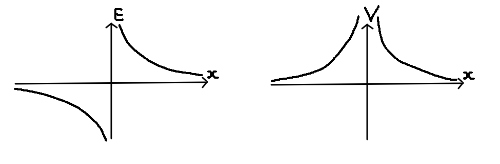
Note that these are the directions of $E$ and $V$ for a point charge $+q$ at the origin. For the $E$ field, positive $E$ indicates that another positive point charge will travel in the $+x$ direction and vice versa, away from the origin. For the $V$ field, you can imagine that another positive point charge will “follow gravity” in the graph and go as low as possible, which is away from the origin.
Circuits
The 3 main quantities of we care about are:
- $V$, defined earlier, the voltage across $2$ points
- $I = \frac{dQ}{dt}$, the current through a wire
- $R = \frac{V}{I} = \frac{\rho L}{A}$, the resistance of a component, where $\rho$ is the intrinsic resistivity of a material.
The power of a component is $P = \frac{dW}{dt} = \frac{d QV}{dt} = V \frac{dQ}{dt} = VI = \frac{V^2}{R} = I^2R$.
Consider two resistors $R_1$ and $R_2$ in series. We have $V_1 + V_2 =V$ and $I_1 = I_2$. Therefore, $R = \frac{V_1+V_2}{I} = \frac{V_1}{I_2} + \frac{V_2}{I_2} R_1 + R_2$.
Consider two resistors $R_1$ and $R_2$ in parallel. We have $V_1 = V_2$ and $I = I_1+I_2$. Therefore, $R = \frac{V}{I_1+I_2} =\frac{1}{\frac{I_1}{V_1} + \frac{I_2}{V_2}} = \frac{1}{\frac{1}{R_1}+\frac{1}{R_2}}$.
A capacitor is a electrical component which stores charge between 2 parallel plates. We define $C = \frac{Q}{V}$, since $V$ is proportional to $Q$, where $V$ is the voltage between two plates of charge $+Q$ and $-Q$.
We have $C = \frac{Q}{V} = \frac{A\sigma}{\frac{d\sigma}{\epsilon_0}} = \frac{\epsilon_0A}{d}$. Note that if we put a dielectric in between the two plates with dielectric constant $\kappa$, then our capacitance will becomes $C = \kappa C_0$.
The power of the capacitor is $\int_0^Q V \, dq = \int_0^Q \frac{Q}{C} \, dq = \frac{1}{2} \frac{Q^2}{C} = \frac{1}{2} CV^2 = \frac{1}{2} QV$.
Consider two capacitors $C_1$ and $C_2$ in series. We have $V_1 + V_2 =V$ and $Q_1 = Q_2$. Therefore, $C = \frac{Q}{V_1+V_2} =\frac{1}{\frac{V_1}{Q_1} + \frac{V_2}{Q_2}} = \frac{1}{\frac{1}{C_1}+\frac{1}{C_2}}$.
Consider two capacitors $C_1$ and $C_2$ in parallel. We have $V_1 = V_2$ and $Q = Q_1+Q_2$. Therefore, $C = \frac{Q_1+Q_2}{V} = \frac{Q_1}{V_1} + \frac{Q_2}{V_2} = C_1 + C_2$.
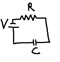
Let $V_C(t)$ denote the voltage across $C$ if $V_C(0)=0$.
We have $\frac{V - V_C(t)}{R} = I = \frac{d}{dt} Q_C = C \cdot V’_C(t)$. Solving the differential equation $RC \cdot V_C’(t) + V_C(t) - V = 0$ gives us $V_c(t) = V(1-e^{-\frac{t}{RC}})$.
We define $\tau=RC$ as the time constant of the circuit.
Magnetism
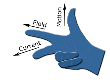
If a particle of charge $q$ is moving through a magnetic field $B$ with velocity $v$, then it experiences a force $\vec F = q(\vec v \times \vec B)$.
If a charge particle allowed to freely move under the influence of a magnetic field, then there will always be a perpendicular force exerted on it by the magnetic field. Since the magnetic field does no work on the particle, since the force is perpendicular to the velocity, the particle must have the same speed, which implies that this particle is undergoing circular motion.
If a particle is under influence of both a magnetic field and an electric field, the forces both things exert on the particle have magnitudes $qvB$ and $qE$. If the electric and magnetic field are orientated correctly, we can allow only particles of a certain velocity $v = \frac{E}{B}$ to move straight when both forces cancel each other.
If a straight wire of length $l$ is carrying current $I$, define $t$ to be the average time for a particle to leave the wire. That mean $q = \frac{dQ}{dt} \cdot t = I \cdot t$ and $v = \frac{l}{t}$. Therefore, $qv = Il$. Therefore, we have $F = IlB$.
Ampere’s Law: $\int_C B_\parallel \, ds = \mu_0 I_{\text{enclosed}}$, where $\mu_0$ is the vacuum magnetic permittivity constant.
For a straight wire carrying current $I$, the magnetic field radius $r$ away from the wire can be calculated using Ampere’s law by taking a circle of radius $r$. We obtain $B = \frac{\mu_0 I}{2\pi r}$. For the direction, use the right hand grip rule.
For loop of current $I$ and radius $r$, the magnetic field at the center is $B = \frac{\mu_0 I}{2r}$. It requires Biot-Savart’s Law to derive, so don’t bother.
For a long solenoid with $n$ loops per meter, the magnetic field at the center can be derived using Ampere’s Law by taking the contour as a $1 ~ \text{m} \times \infty ~\text{m}$ rectangle which has a $1~\text{meter}$ portion in the middle of the solenoid. From Ampere’s Law, we can derive that $E = \mu_0 nI$.
If two straight wires both carry currents $I_1$ and $I_2$, they will exert force on each other with force per length of $\frac{F}{l} = I_1B_2 = \frac{\mu_0 I_1I_2}{2 \pi d}$. If the current are the same direction, they attract each other. Otherwise, they repel each other.
Consider a rectangle piece of wire that is fixed at two points shown below.
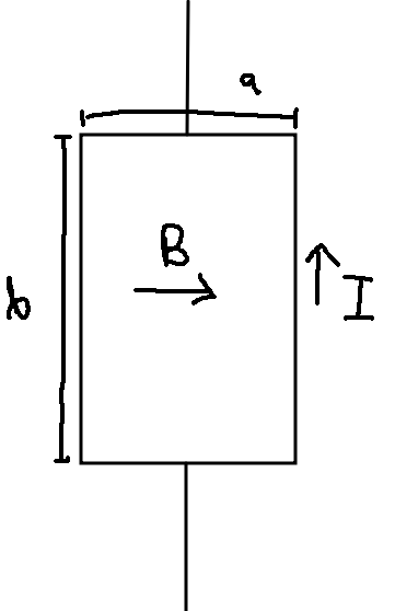
While the net translation force of the entire wire is $0$ due to symmetry (applies to any closed loop), the net torque is not. The left side of the loop has a upwards velocity and the right side has a downwards velocity. The net torque in this case is $\tau = 2 \cdot \frac{a}{2}(IbB) = IAB$, where $A$ is the area of the closed loop. Actually, we can prove that this formula holds for any closed loop by cutting the closed loop into small rectangle loops. If we have $N$ loops, the formula just becomes $\tau = NIAB$.
Induction
$\Phi_B = B \cdot A$ magnetic flux intuitively the number of B field lines passing through some area.
Faraday’s Law states that $\varepsilon = \frac{d \Phi_B}{d t}$.
For the direction, Lenz’s law states the directions are reversed when creating motion against creating electricity. Use the left hand grip rule.
We can make a generator. Suppose a loop of wire is rotated about a permanent magnetic field. Then $\Phi_B$ would be something like $\sin(t)$, so that $\varepsilon = \cos(t)$.
An inductor is an electrical component that opposes sudden changes in current. It is a piece of coiled wire. Define the self-inductance as $L = \frac{\Phi_B}{I}$, since $\Phi_B$ is generated by the current to the current $I$ itself. By Faraday’s Law, $\varepsilon = \frac{d \Phi_B}{dt} = L \frac{d I}{dt}$.
The self-inductance is proportional to $N^2$ if it is made of $N$ turns close together. If the flux is in a region containing a magnetic material with relative permeability $\kappa$, then the inductance would increase to $L = \kappa L_0$.
The power of the inductor is $\int_0^I E = \int_0^I P \, dt = \int_0^I VI \, dt = \int_0^I L \frac{dI}{dt} I \, dt = \int_0^I LI \, di = \frac{1}{2} LI^2$.
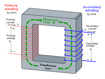
The above is a ideal transformer. We have $\varepsilon_p = N_p \frac{d\Phi_B}{dt}$ and $\varepsilon_s = N_s \frac{d\Phi_B}{dt}$ by Faraday’s Law. Therefore, $\frac{V_p}{N_p} = \frac{V_s}{N_s}$. By conservation of energy, we have $V_pI_p = V_s I_s$.
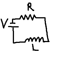
Let $I(t)$ denote the current through the entire circuit where $I(0)=0$.
We have $V = V_R + V_I = R \cdot I(t) + L \cdot I’(t)$. Solving the differential equation $\frac{L}{R} \cdot I’(t) + I(t) - \frac{V}{R} = 0$ gives us $I(t) = \frac{V}{R}(1-e^{-\frac{R}{L}t})$.
We define $\tau=\frac{L}{R}$ as the time constant of the circuit.
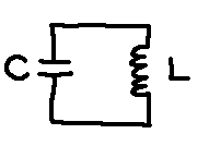
The initial state for this circuit is $V_C(t) = V_{\text{max}}{}$ and $I(t)=0$.
We know by conservation of energy that $P_C + P_I = \frac{1}{2} CV^2 _ C + \frac{1}{2} LI^2 _ T$ is a constant value, which from our initial conditions we know is $\frac{1}{2} CV_{\text{max}}^2$.
We also have that $V_C = V_T = L \cdot I’(t)$. Therefore, we have $C(L \cdot I’(t))^2 + LI(t)^2 = CV^2$, which simplifies to $LC \cdot I’(t)^2 + I(t)^2 = \frac{C}{L}V_{\text{max}}^2 = I_{\text{max}}^2$.
The solution to this differential equation is $I(t) = I_{\text{max}} \sin( \frac{1}{\sqrt{LC}}t)$ and $V_C(t) = V_{\text{max}} \cos( \frac{1}{\sqrt{LC}}t)$.
Note that we have the period of the oscillations being $\omega = \frac{1}{\sqrt{LC}}$.